Compound Online Monitoring Insulation Device
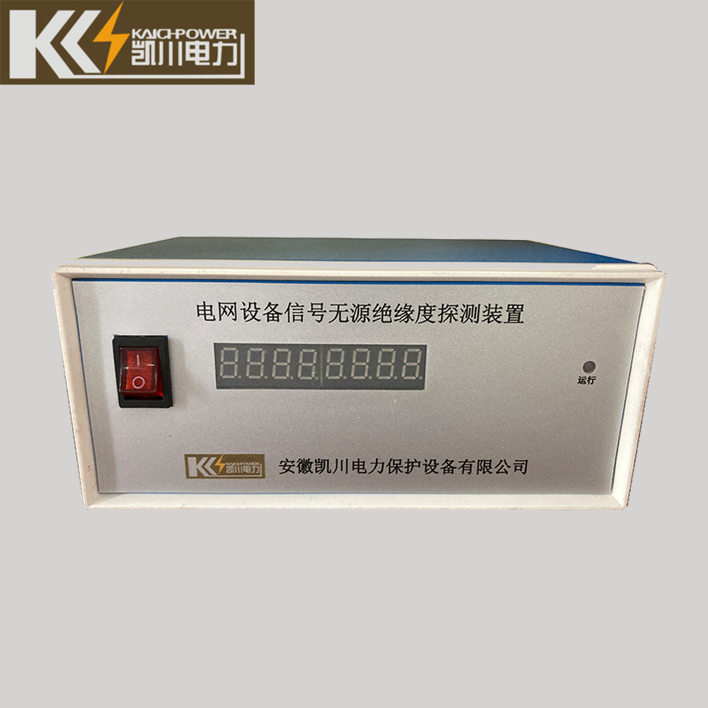
Compound Online Monitoring Insulation Device(KCIM-F/G-Q-R) power grid operating equipment insulation online monitoring device is a device that can monitor the insulation status of high-voltage power cables, arresters, insulators, vacuum switches and other objects online.
Defects and hidden dangers of accidents, control of sudden insulation accidents, and monitoring of insulation performance of electrical equipment provide effective information to ensure the safe and reliable operation of equipment.The device is easy to install, simple to operate, has strong real-time performance and more real and accurate monitoring information, and is widely used in 0.4kV ~ 35kV power systems. The device is controlled and managed by a high-performance single-chip microcomputer, and the human-computer interaction interface is displayed on a 5.0 color screen. When the device diagnoses the failure of the running equipment, the indicator light and buzzer will alarm at the same time, and the alarm relay will act, so that the equipment maintenance personnel can know the insulation status of the equipment in time. In addition, the device also has an RS485 communication interface to facilitate communication with the host computer.
Compound Online Monitoring Insulation Device of Contents
Product Introduction
1.1 Introduction to Human-machine Interface
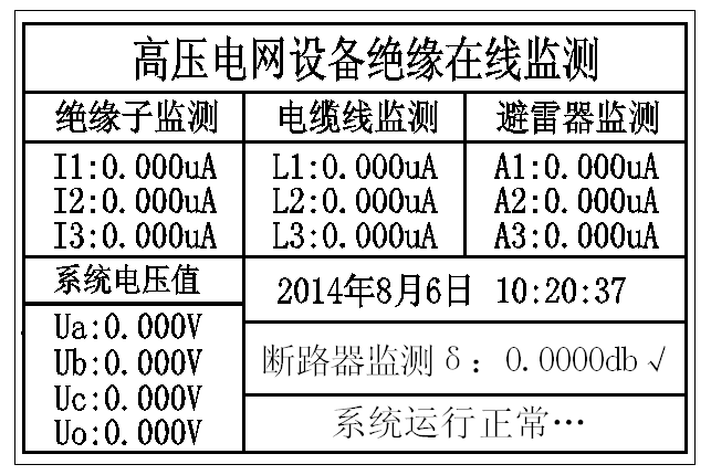
In standby mode, the LCD display displays relevant information when the unit is operating or when the user is operating. The above picture shows the main interface of the LCD screen, which displays the current status, current time and product name of the monitored object. When the three-phase voltage on the secondary side of the PT is not connected to the monitoring device or the system has no faults, and the three-phase voltage is connected to the monitoring device normally and the leakage current does not exceed the alarm threshold, the main interface displays “system running normally”; the three-phase voltage is normal When the monitoring device is connected and the leakage current exceeds the alarm threshold, the main interface displays the fault type and related information: the color of the corresponding leakage current changes from yellow to red, and the corresponding indicator lights are on, corresponding to the output of the alarm node. (Note: This device adopts plug-in interface design, and the device is full-function monitoring. If the leakage current value of the object monitoring corresponding to the menu interface is displayed in red, it means that the device does not include the object monitoring)
There are 7 indicator lights on the left side of the LCD screen of the man-machine interface: from top to bottom on the left side are the running lights, the cable L fault alarm indicator, the arrester A fault alarm indicator, the insulator I fault alarm indicator, and the vacuum switch S fault alarm Indicator light; arc fault alarm indicator light, metal fault alarm indicator light.
The buttons on the right side of the man-machine interface are as shown in the figure below: reset button, menu button, up button, down button, left button, right button, cancel button, and OK button. The functions of each button are as follows:
- The function of the “reset” key is: when the parameter setting is changed, and when the system needs to be reset, press the “reset” key to reset the system.
- The function of the “menu” key is: function menu setting;
- The function of the “up” key is to decrease the value of the selected data by “1” during the function setting process;
- The function of the “down” key is to increase the value of the selected data by “1” during the function setting process;
- The function of the “left” key is to move the selected data bit to the left by one bit during the function setting process;
- The function of the “right” key is to move the selected data bit to the right by one bit during the function setting process;
- The function of the “Cancel” key is to exit the menu at this level and return to the previous menu during the menu operation;
- The function of the “OK” key is: press the “Menu” key on the main interface to enter the main menu for function setting, and it is used to confirm the current setting and enter the next sub-menu setting during the function setting process;
Note: The date and time will not change after reset, please use it with confidence.
1.2 Alarm Introduction:
When the device detects the deterioration of the insulation performance of the monitored object, the device fault indicator lights up, and the buzzer and relay act.
Note: The relay output terminal provides passive nodes, which can be used for external alarm lights or alarm bells.
1.3 Functions Operation
When the man-machine display interface, press the OK key to enter the setting menu interface as shown below:
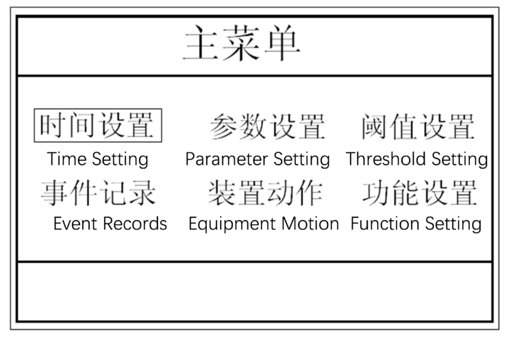
(1) Menu Structure
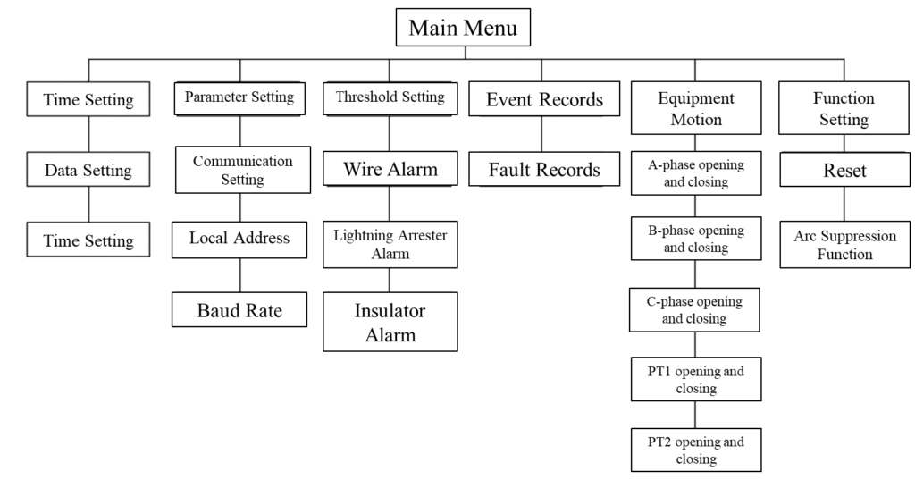
(2) Date Setting
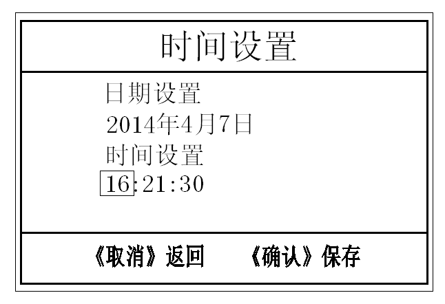
In the time setting menu, use the “Left” and “Right” keys to move the cursor to select “Date Setting” or “Time Setting”, and press the “Left” and “Right” keys to move the cursor to any number in a row. The number is displayed in yellow. Use the “up” and “down” keys to adjust the number to increase or decrease. After the adjustment is complete, confirm to save. Press the “Enter” key to set the clock will be stored in the memory, press the “Return” key to cancel this operation
(3)Parameter Setting
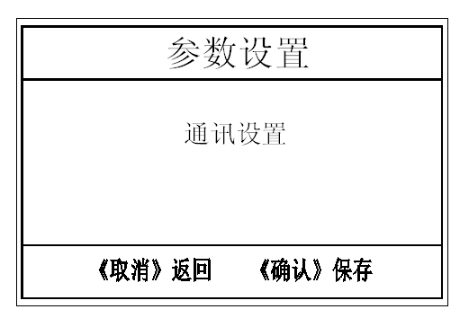
The parameter setting menu includes the communication setting function. Use the “left” and “right” keys to move the cursor to select “local address” or “communication baud rate”, and press the “up” and “down” keys to set the local communication address , the setting range is from 01 to 99, the selectable baud rate is 1200, 2400, 4800, 9600, press the “Enter” key to save the setting, and press the “Return” key to cancel this operation.
(4) Threshold setting (dedicated for factory debugging)
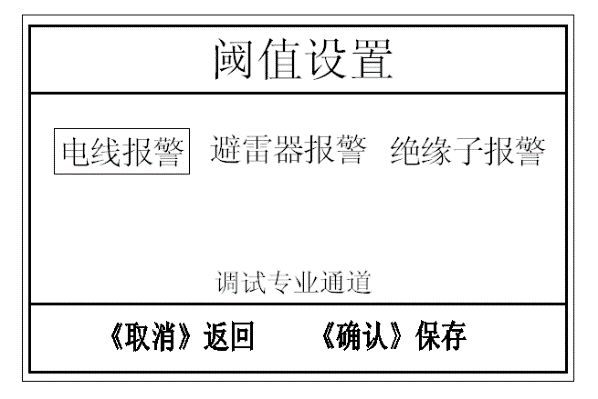
When setting the harmonic threshold, up to 51 harmonics can be set. After the adjustment, press the “Enter” key to save the setting, press the “Return” key to cancel this operation, and the screen returns to the main menu. Without three-phase current sampling, this function is not used. Before the product leaves the factory, our company has checked and adjusted the parameters, and incorrect adjustment and operation may cause the product to not work properly.
(5) Event Records
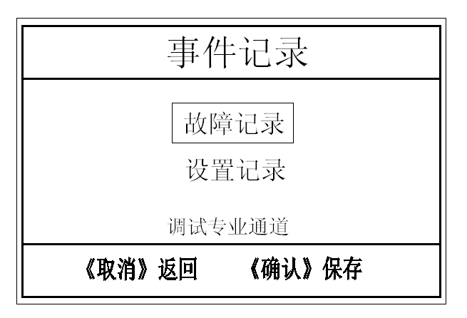
In the “fault record” menu, you can view the fault information that occurred in the history. Press the “up” and “down” keys to scroll through the records, and you can query the current fault records of 50 pages at most. Press the “Back” key to return the screen to the main menu.
(6) Equipment Motion
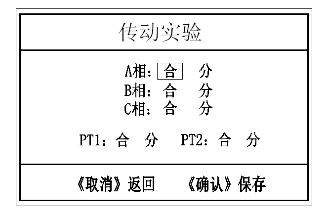
Use the “Up” and “Down” buttons to select the phase to be tested and the opening and closing status. After pressing the “Confirm” button, the controller sends a signal to command the contactor to open and close, and the operation is prohibited in the “Commissioning” status. Can be used with other controllers.
(7) Function Setting
This function is an extension function and has not been opened yet.
2. Technical indicators
Working power | 85~264VAC, 120~370VDC |
Insulation performance | between the shell and the terminal > 100MΩ |
Enclosure Protection | IP43 |
Working temperature | -20℃~65℃ |
Working humidity | ≤95%RH |
Applicable voltage level | 0.4~35KV |
Current signal | Ix or In=70µA~700mA |
Voltage signal | Un=3V~300V |
Dielectric loss | tanδ=-500%~500% |
Capacitance | Cx=10pF~0.3µF |
Capacitance ratio | Cx:Cn=1:1000~1000:1 |
Resistive current | Irp=10µA~10mA |
Capacitive current | Icp=100µA~300mA |
Phase range | α=-180°~180° |
Frequency range | f=45Hz~55Hz |
Leakage current measurement range | 50µA~700mA |
3. Reference Standard
GB/T 156-2007 standard voltage; IEC 60034 rotating electrical machine;
IEC 60060-1989 High Voltage Test Technology;
IEC 60099-2006 Lightning arrester; GB/T 775-2006 Test method for insulators;
GB 311.1-1997 Insulation coordination of high-voltage power transmission and transformation equipment;
GB/T 311.2-2002 Insulation coordination part 2: Guidelines for the use of insulation coordination for high-voltage power transmission and transformation equipment
GB/T 2951-1997 General test methods for cable insulation and sheathing materials;
GB/T 3048-1994 Test method for electrical performance of wire and cable;
GB/T 7354-2003 Partial discharge test;
GB/T 2421-2424 Environmental test procedures for electrical and electronic products;
4. installation instructions
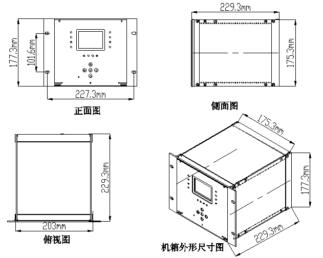
Mounting Dimensions (Embedded Type)
Hole size: 175.5 mm (height) × 207 mm (width);Installation size: 101.6mm (height) × 227.3mm (width) × 229.5 mm (depth);
Installation dimensions must be indicated: depth, width, height
4.1 Installation method and main components:4
- The main part (that is, the control display part) is installed on the instrument door panel of the switch cabinet or the secondary terminal room;
- The accessory part (that is, the sensor that collects the leakage part) is installed in the high-voltage cable room;
- The main body and accessories are connected by shielded twisted pair, and the standard configuration is 5 meters;
- The whole device consists of three parts: controller, high-precision micro-current sensor and shielded twisted pair.
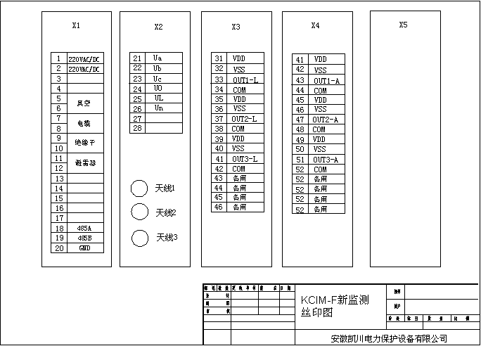
4.2 Description of device wiring terminals and sensor wiring:
shielded twisted pair | Device terminal number | Sensor terminal |
red | 31(VDD) | Power+ |
black | 32(VSS) | power supply- |
yellow | 33(OUT1) | output M |
White | 34(COM) | Power 0 |
red | 51(VDD) | Power+ |
black | 52(VSS) | power supply- |
yellow | 53(OUT1) | output M |
White | 54(COM) | Power 0 |
4.3 Connection of sensor to cable shield
Pass the shielding layer of the monitored cable through the hole of the microcurrent sensor and ground it, paying special attention to only pass through a single turn, as the picture shows:

Arrester wiring: pass the ground wire of the arrester base screw through the high-precision micro-current sensor and then ground
Vacuum switch wiring: Antenna 123 is respectively connected to yellow, green and red SMA wires
4.4 Installation precautions
- Wiring strictly in accordance with the function definition of the rear-view terminal;
- Overall dimensions and opening dimensions are subject to the actual order;
- The installation method is: embedded installation.