Medium-Voltage Circuit Breakers (OEM)
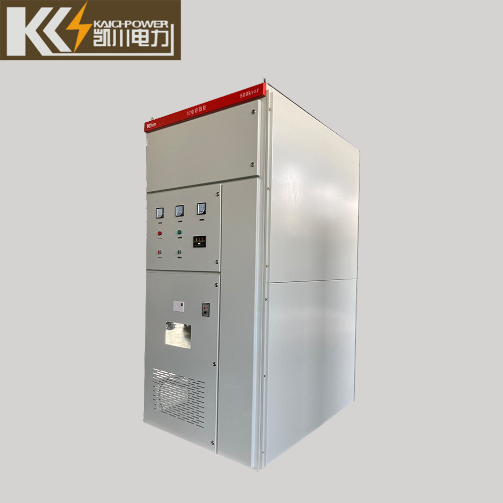
High and Low Voltage Reactive Power Compensation Device
The device is a new generation of reactive power compensation device using the MSC technology of the contactor switching capacitor bank and the TSC technology. The device collects the voltage and current signals of the power grid, and analyzes them in real time by the controller.
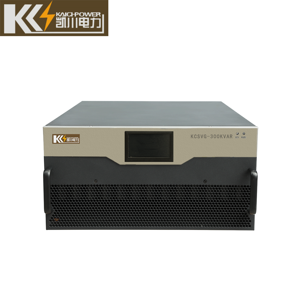
It adopts the zero-crossing switching technology, and uses the high-power non-contact switching switch to automatically, quickly and without impact switching capacitor banks to compensate for the inductance of the power grid. Static Var Generator, reduce losses, improve the quality of power grid power supply and improve economic benefits. In addition, the “self” protection function of the device itself is complete, and it can respond quickly to abnormal situations in operation to ensure the safe operation of the device; the switchgear of the device has multiple forms, which can be easily connected with existing power distribution cabinets and switches. switchgear and other switchgear are combined
Application
At present, most of the loads on the power grid are inductive loads, so the reactive power on the power grid mainly refers to the inductive reactive power generated by these inductive loads, so we can use the method of parallel (series) capacitors to compensate the inductive load caused by the inductive load. Reactive power to achieve the purpose of reactive power compensation and providing power factor. Considering the influence of harmonics in the power grid, this product can be equipped with a reactor of appropriate capacity according to customer needs, so as to greatly reduce the influence of harmonics and achieve the purpose of anti-harmonics.
The K C Q B reactive power compensation device is connected in parallel with the low voltage side of the transformer, and adopts the relatively mature MSC and T S C technologies. Q1. Compare Q1 with the threshold Q2 set in the control, and refer to the voltage change of the power grid, automatically select the compensation capacity that can achieve the compensation effect, and issue commands, and the zero-crossing trigger module controls the on and off of the thyristor, fast and without The shock realizes the switching and cutting of the capacitor bank
Standard
ICE439 Low-voltage switchgear and controlgear
GB7 251 Low-voltage switchgear
GB12747-91 Self-healing low-voltage parallel capacitors
GB 50227-2008 Design Specification for Parallel Capacitors
G B3983.1-89 Low Voltage Shunt Capacitors
GB15 576- 2008 Low-voltage complete set of reactive power compensation device
GB/T 12326-2008 Power Quality Voltage Allowable Fluctuation and Flicker
GB /T 14549- 1993 Power Quality Harmonics of Public Grid
Technology Paraments
Compensation voltage level: 0.4kV 0.66kV 0.69kV.
Rated frequency: 50Hz.
Rated compensation capacity: 40 kvar~1440kvar.
Target power factor: 0.9~1
Operating voltage range: 0.8~1.1UN.
Capacitor wiring method: delta “△” or star “Y”,
Measurement accuracy: The accuracy of the main electrical parameters is 0.5, and the measurement accuracy of power and electricity is 1.
Switching action corresponding time: less than 20ms.
Maximum allowable current: allow long-term operation under 1.3IN,
Switching mode: The controller automatically switches and manually switches.
Maximum allowable voltage: allow long-term operation at 1.1UNTF,
Reactor reactance rate selection: 1% to 14% (determined according to the harmonic status of the power grid or according to user requirements); for suppressing more than 5 harmonics, the optional reactance rate is 6%; for suppressing more than 3 harmonics, it can be The selected reactance rate is 12%.
The cabinet body is made of high-quality cold-rolled steel, with good flatness, and the outer surface is sprayed with plastic, which has strong anti-corrosion ability; the internal frame is made of galvanized steel plate coated with aluminum-zinc steel plate to ensure better electrical conductivity and corrosion resistance. The device adopts a user-universal matching cabinet, which makes the installation, use, maintenance and other aspects of the user more convenient, and can also be designed according to the user’s requirements.
Automatic control: KCDK low-voltage automatic reactive power compensation controller is adopted.
Switch: knife switch, molded case circuit breaker, knife fuse switch.
Transformer: Current Transformer.
Capacitor: KC-BKMJ type low voltage parallel capacitor.
Reactor: KC-CKSG type low-voltage series reactor can choose reactors with different reactance ratios according to the situation.
Switching switch: special contactor for switching capacitor, KCFK type compound switch and KCDB type thyristor (using imported thyristor).
Protection components: BKPD arresters, fuses, miniature circuit breakers.
KCDK controller technical parameters
Measuring system: three-phase
Measuring voltage: three-phase voltage or two-phase voltage (A, C voltage)
Measuring current: 0~5A three-phase current or one-phase current (B-phase current)
Frequency: 50HZ
Current input impedance: <0. 1Ω
Number of output circuits: 12, 16
Output contact capacity: DC 12V 6 0mA/branch, AC22 0V 5A/branch
Working voltage: AC22 0V
Overvoltage protection setting range: 400V~4 80V step size 2V
Undervoltage protection setting range: <30 0V
Absorbed power consumption: voltage 0.2 VA/phase current 0.1 VA/phase
Target power factor setting range: 0.9~1.00 step size 0.01.
The sampling physical quantity is reactive power, and there is no switching oscillation and no compensation dead zone during operation.
Compensation method: separate-phase compensation/three-phase common compensation/comprehensive compensation.
With manual compensation/automatic compensation two working modes
Zero-current switching – using high-power thyristor current zero-crossing switching technology to achieve no inrush current, no impact, no arc re-ignition, after the capacitor is removed, it can be switched on again without discharge, and can be switched frequently;
Fast dynamic response – fast tracking system load reactive power changes, real-time dynamic response switching, system response time ≤ 20ms;
The compensation effect is obvious – within the specified dynamic response time, the multi-level compensation is in place at one time, and the power factor after compensation is >0.95;
Use electronic switches to achieve non-contact switching, no noise, no wear;
Intelligent control – using microcomputer control, intelligent switching mode, to achieve unattended, and with microcomputer communication interface RS232/RS485, remote telemetry, remote signaling, remote control (optional);
Complete protection functions – with various digital functions such as overcurrent, overvoltage, undervoltage, and temperature overrun. At the same time, the device can automatically exit in case of external failure or power failure, and automatically recover after power supply;
Compensation method – three-phase symmetrical load compensation, three-phase asymmetrical load compensation and common division combined compensation;
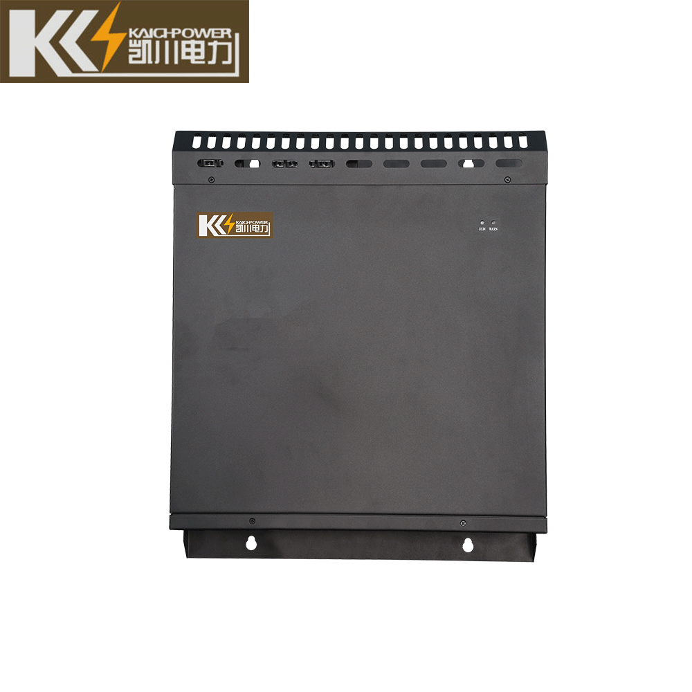
Good heat dissipation effect – the device is installed with a cooling fan, which improves the ventilation and heat dissipation capacity of the device;
Flexible configuration of capacitor banks – the capacitance of each group can be configured in 1: 1: 1, 1: 2: 2, 1: 2: 4 and other configuration methods, which can meet the requirements of various reactive power requirements;
| Model | Vlotage (kV) | Installation capacity (kvar) | Number of circuits | Circuit capacity(kvar) | Reactance rate | Switchgear size(mm) | Switchgear quantity(pieces) |
| KCQB-0.4-120 | 0.4 | 120 | 4 | 30 | 6% | 800*800*2200 | 一 |
| KCQB-0.4-240 | 0.4 | 240 | 6 | 40 | 6% | 1000*1000*2200 | 一 |
| KCQB-0.4-240 | 0.4 | 240 | 8 | 30 | 6% | 1200*1000*2200 | 一 |
| KCQB-0.4-300 | 0.4 | 300 | 6 | 50 | 6% | 1000*1000*2200 | 1 |
| KCQB-0.4-360 | 0.4 | 360 | 6 | 60 | 6% | 1000*1000*2200 | 1 |
| KCQB-0.66-240 | 0.66 | 240 | 3 | 80 | 6% | 1000*1000*2200 | 一 |
| KCQB-0.66-320 | 0.66 | 320 | 4 | 80 | 6% | 1200*1000*2200 | 1 |
| KCQB-0.69-240 | 0.69 | 240 | 3 | 80 | 6% | 1000*1000*2200 | 1 |
| KCQB-0.69-320 | 0.69 | 320 | 4 | 80 | 6% |
Environmental Conditions
Temperature: -15°c – +45°C.
Relative humidity: ≤85% (+ 25°C).
Altitude: no more than 2000m.
Installation inclination: no more than 5° away from the reference position.
Installation environment: the surrounding medium is free of explosion and flammable hazards, no gas that can damage insulation and corrode metals, and no conductive dust;
The installation site is free from severe vibration and turbulence.