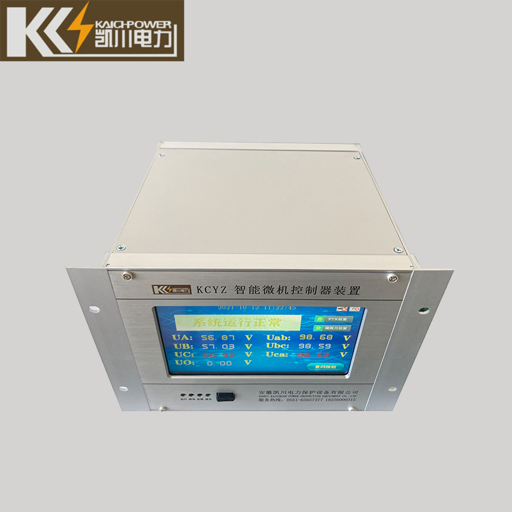
Intelligent Microcomputer Controller
Intelligent controller developed by our company for the comprehensive overvoltage protection device. The dual-core microprocessor used in this product has a powerful improved Harvard structure and digital signal processor calculation function, so it can use DSP’s high-speed and repeated data processing capabilities to achieve Fourier analysis, by analyzing the secondary voltage of the voltage transformer PT.
Collect, judge, analyze various grounding states of the power grid in a timely and accurate manner, and take corresponding actions. At the same time, the powerful logic operation capability of the microprocessor is used to quickly realize the functions of liquid crystal display, remote communication and data protection.
Intelligent Microcomputer Controller of Contents
Functions and Features
- Modular design, compact structure, advanced technology, high-speed DSP core processor ensures real-time operation and action accuracy;
- Monitor the system status in real time, make accurate judgments on abnormal operating conditions (loss of voltage, low voltage, overvoltage, grounding, resonance, etc.), and take timely actions;
- The industrial standard RS-485 communication interface can transmit the operating status of the system to the upper computer;
- Fault recall function, display the last 20 historical fault records;
- It has good electromagnetic compatibility and is suitable for application in complex environments with strong electromagnetic interference;
- Dual hardware watchdog circuits ensure the reliability of software operation;
- Chinese LCD display, clear running status, menu-based operation, easy to use.
Signal Light and Button Description
- Operation: normal operation indicator, flashing frequency 1Hz;
- Alarm: fault indication, the system will turn off after normal operation;
- Communication: communication instructions with the background;
- ←↑↓→: Menu selection and parameter adjustment buttons;
- Confirm: Enter the lower menu and confirm the parameter setting button;
- Cancel: Return to the previous menu and cancel the parameter setting button;Reset: System restart button
Working Principle
This product is designed based on the voltage signal provided by PT. The overall structure of the device is shown in the figure below:
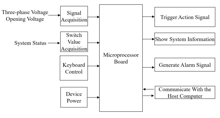
It is based on the zero-sequence voltage appearing in the power supply system with the neutral point-to-ground insulation when the line fails, and the zero-sequence voltage is used as the starting signal to start the calculation, and then the logic analysis and calculation are performed according to the voltage of each phase when the fault occurs, and the judgment is made. The phase difference and grounding attribute of the ground fault occurrence, and then make corresponding processing according to the judgment result.
Working Environment
Altitude: less than 2000m, up to 4000m under special circumstances;
Working environment temperature: -10℃- 60℃;
Air relative humidity: 90% (25°C), 50% (40°C)
There shall be no corrosive gas, steam, conductive dust, explosive gas and insulating gas in the place of use;
The installation site is protected from wind, rain and dust.
the device terminal wiring diagram
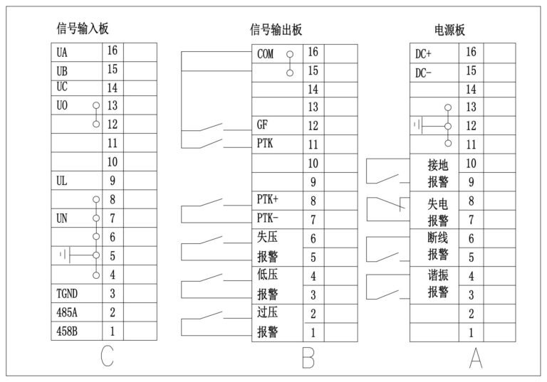
1. Terminal A is the device power board:
- A15~A16 provide power input interface: AC/DC 220V, 110V;
- A11~A13 are ground terminals;
- A9~A10 are grounding alarm terminals, they are closed when the metal is grounded or the arc is grounded;
- A7~A8 are power-loss alarm terminals, when the device loses power, it will be closed;
- A5~A6 disconnection alarm terminal, when PT disconnection, it will be closed;
- A3~A4 are resonance alarm terminals.
2. Terminal B is the signal output switch board:
- B15~B16 are the common terminals of digital signal;
- B12 is the auxiliary contact input interface of the isolation switch;
- B11 indicates whether the PTK switch is closed;
- B7~B8 control the opening and closing operation of the PTK switch.
- B5~B6 system voltage loss alarm;
- B3~B4 system voltage low voltage alarm;
- B1~B2 system voltage overvoltage alarm;
3. Terminal C is the signal input board:
- C14~C16 are the input terminals of the PT secondary three-phase main winding;
- C12~C13 are the neutral point input terminals of the PT secondary three-phase main winding;
- C7 and C9 are PT open triangle input terminals;
- C4~C6 are grounding common terminals;
- C3 is the 485 communication interface ground;
- C1~C2 are 485 communication interfaces, the computer can access the device through this interface, and the microcomputer controller will give a response signal to tell the computer the running status of the controller at this moment.
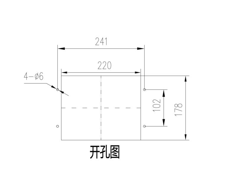
Installation size (mm) Depth: 200mm
Communication Protocol
MODBUS (RTU mode) communication protocol, using RS-485, baud rate 9600BPS, 1 start bit, 8 data bits, no parity, 1 stop bit, a total of 10 bits. When XHG leaves the factory, the site address and communication baud rate have been set, and the site address is 01.
The CRC check weight is CRC-16=X16+X15+X5+1
1. The master station asks the downlink message format:
ADD | Function code | Start address | Word length | 16 bit CRC check code | |||
ADD | 03H | 00H | 00H | 00H | 06H | CRC Low | CRC High |
2. The slave station responds to the upstream message format:
| ADD | Function code | word length | word length | 6-bit CRC check code | |
| ADD | 03H | 0CH | 12 | CRC low | CRC high |