

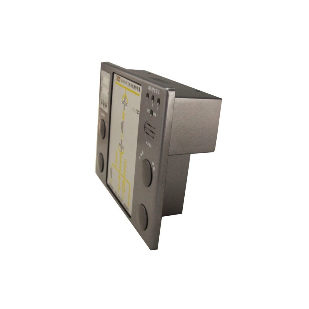
The switch gear intelligent control device is used for 3~35KV low and miduem switchgear,indoor central switchgear, handcart switchgear, fixed switchgear, ring network switchgear and other switch gears. It has a simulation diagram, live display, opening and closing status indication, grounding switch indication,
Energy storage indication, handcart position indication, voice error prevention prompt, digital display of temperature and humidity, RS485 remote communication interface and many other functions.The product is controlled by microprocessor, and the internal components are high-quality imported industrial-grade brands, which have the advantages of stability and reliability, long life and strong anti-interference. Compared with traditional analog display signs, this product has the advantages of intuitive display and convenient operation.
1.Introduction
Table of Contents
1.1 Product Functions and Features
- High degree of intelligence: It can display the status of the circuit breaker, the position of the handcart, the status of the isolation knife and the grounding knife, the energy storage display, etc. (it can meet various display functions according to user requirements). It can also be judged whether the indicating switch trolley is between the test position and the working position or outside the gear.
- It can indicate whether the three phases A, B, and C are live, and provide live locking contacts. The ‘lock’ can only be released when the charged display is in an unpowered state.
- Closing/opening transfer switches, local/remote transfer switches and energy storage transfer switches can be arranged on the panel according to user needs.
- Using digital display for temperature and humidity, and directly displaying the state in the gear.
How to control:
1-2 heaters can be provided. When the ambient humidity is ≥90%RH, turning on heaters, and when it is ≤75%RH, turning off heaters; when the ambient temperature ≥40℃, the heater exits unconditionally. For the temperature and humidity in the gear, users can also set it according to their need.
- Disconnection alarm: If any one of the heaters is disconnected, the disconnection indicator light is on.
- Mistake-proof voice prompt: If the operator does not close the grounding switch by mistake at the test position, the device prompts “Please disconnect the grounding switch”. If the operator pushes or pulls out the handcart by mistake at the closing position of the circuit breaker, the device prompts “Please open the circuit breaker”.
If the operator has two wrong operations as above at the same time, the device willprompt “Please disconnect the circuit breaker. Please disconnect the grounding switch”.
3.Communication function: RS485 interface, MODBus protocol mode, the communication baud rate up to 9600. It can form a timely microcomputer anti-mistake monitoring system with other equipment in the substation.
1.2 Technical Parameters
- Working power supply: AC220V, DC110V, DC220V
- Working environment: -20℃~+60℃
- Control range: 0℃~+99℃
- Control accuracy: Temperature ±2℃, Humidity ±5%RH
- Power consumption: ≤5W
- Communication: RS485 baud rate 1200 2400 4800 9600 (optional)
- Dielectric strength: greater than AC2000V between the shell and the terminal
- Insulation performance: greater than 1000MΩ between the shell and the terminal
- Shock resistance: 10~55~10HZ 2g 1min
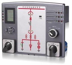
2. Instrument Function Introduction
2.1 Instrument Panel Diagram
01 Circuit breaker closing
02 Circuit breaker opening
03(1) 03(2) Test position
2.2 Instrument Terminal Wiring Diagram
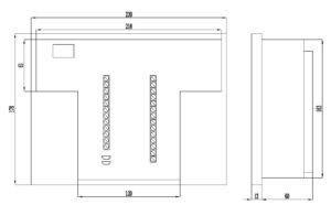
3. Installation Method
- Installation method of the instrument: embedded
- Appearance and installation dimensions of the instrument: Hole size: 220X165 (unit: mm)
3.1 Installation method of temperature and humidity sensor:
- Using fixed installation
- The connection between the sensor and the instrument adopts the interface plug-in method
3.2 Specifications of charged sensor:
- LED ignition voltage (kV): busbar voltage × 0.15
- Locking start and control voltage (kV): busbar voltage × 0.65
4. Operation Instructions
4.1 Press the ‘enter’ key to enter the setting
- Display 00.1 means mode 1: set temperature
- When the temperature > the set value, the heater is prohibited from working;
- When the temperature < set value -2 (return difference), the heater is allowed to work;
- When the temperature is greater than the set value +10, the overheating indicator light is on, and the “overheating alarm” terminal on the back is turned on;
- When the temperature is less than the set value + 5 (hysteresis), the overheating indicator is off and the output is stopped.
- In mode 1, the user can set the reference temperature by himself:
- Press the ▲ key to increase the base temperature by 5°C;
- Press the ▼ key to lower the base temperature by 5°C.
- The factory default reference temperature is 40°C.
4.2 Press the ‘enter’ key again
- Display 00.2 means Mode 2: set humidity
- When the humidity > the set value and the ambient temperature is normal, the heater works and the heating indicator light is on;
- When the humidity < the set value -15 (return difference), the heater stops working;
- This machine has the function of disconnection detection, when the humidity > set value, the ambient temperature is normal;
- When the heater fails to start normally, the disconnection indicator light is on, indicating that the heater is disconnected.
- In mode 2, the user can set the reference humidity by himself:
- Press the ▲ key to increase the base humidity by 5%RH;
- Press the ▼ key to reduce the base humidity by 5%RH.
- The factory default reference humidity is 90%RH.
4.3 Press the ‘enter’ key again
- Display 00.3 Indication style Set communication address
- For example, 00.1 means the local address is 1.
- In mode 3, the user can set the communication address of the machine by himself:
- Press ▲ to add 1 to the address;
- Press ▼ to decrease the address by 1.
The factory default communication address is 01, and the user needs to set it on site
4.4 Press the ‘enter’ key again to enter the normal acquisition mode
5. Using and Debugging Methods
- The products are all embedded structures, only need to make holes on the switchgear panel, and then fix it on the panel;
- After connecting the wires according to the terminal diagram and proofreading correctly, turn on the power supply;
- Disconnect and short-circuit each digital input to check whether its function is normal;
- Temperature and humidity control function, blow air to the sensor with the mouth until the heating indicator light is on, and the heating output end is turned on;
- The input terminals of the live display are respectively connected with high-voltage live sensors. When any phase of high-voltage is live, the corresponding high-voltage live red indicator light is on. When three phases are not live, the lock release green indicator light is on.
6. Transportation and Storage
- The transportation and unpacking of the intelligent control device of the switch cabinet should not be severely impacted, and should be transported and stored in accordance with the provisions of GB/T15464 “General Technical Conditions for Packaging of Instruments and Meters”.
- The intelligent control device of the switch cabinet should be stored in the original packaging. The ambient temperature of the storage place is 0℃~+40℃, the relative humidity does not exceed 85%, and there is no corrosive gas in the air.
- The switchgear intelligent control device is stored in the warehouse and should be placed on the bench, and the stacking height should not exceed 5 boxes. After unpacking, the stacking height of a single packaged switchgear intelligent control device should not exceed 3 packages.
7. Product Ordering Instructions
- When ordering, please provide corresponding instructions and parameters:
- Provide a plan diagram;
- Product name, model and quantity (refer to the naming method and meaning), please specify special functions;
- Device input power: AC: 220V DC: 110V DC220V;
- Temperature and humidity sensor wiring length;
- Heater power and quantity (the heater voltage is AC220V);
- Consignee, zip code, address, consignee and contact number, etc.