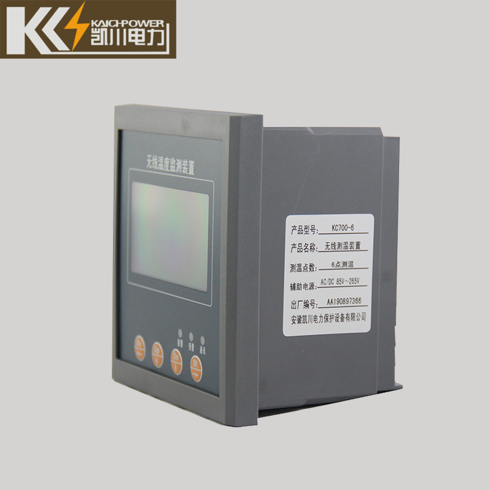
wireless temperature monitoring device for low medium switchgear
During the long-term operation of high-voltage equipment in the power system, problems such as surface oxidation and corrosion, loosening of fastening bolts, and aging of contacts and busbar connections often occur, resulting in equipment overheating and even serious accidents. However, there are exposed high voltages in the switch cabinet, the space is closed and narrow, and manual inspection and temperature measurement cannot be carried out.
Traditional temperature measurement methods cannot effectively solve this problem.The wireless contact temperature measuring device installs the temperature measuring sensor on the electrified contact in the switch cabinet, and uploads the temperature data to the receiving end by wireless transmission, and the receiving terminal displays the temperature data through the liquid crystal, and uploads the temperature data to the customer through the RS485 bus. backend software. When the abnormal temperature of the contact is detected, the system can automatically and remotely alarm, so as to eliminate the hidden danger in time.
wireless temperature monitoring device for low medium switchgear
wireless temperature monitoring device of Contents
Technical Indicators
- Working temperature: -20℃~+65℃
- Working humidity: ≤95%RH
- Altitude: <3KM
- Dielectric strength: ≥AC2000V
- Insulation performance: ≥100MΩ
- Anti-electromagnetic interference performance: in line with IEC255-22 standard
- Working power supply: AC85~265V/DC110~300V
- Temperature measurement accuracy: ±1℃
- Wireless contact temperature measurement range: -55℃~+125℃
- Temperature measurement cycle time: 5S
- Communication method: RS485 communication interface, RTU communication protocol of MODBUS
- The open distance between the transmitting module and the receiving module: <100 meters
- Temperature measurement points: 1 to 12 points
- Temperature measurement life: 3.6V lithium battery in the temperature measurement transmitter, the normal working time is more than 5 years
Functions of KC700
- Real-time data display of online temperature of multiple switch contacts;
- Alarm temperature upper and lower limit setting data display;
- Event recording function: record nearly ten over-temperature alarm data, all data are recorded with time stamp;
- Current date and time setting function;
- Communication address and baud rate setting function;
- The system can automatically and remotely alarm over temperature;
- Equipment self-check function and automatic recovery function, when the equipment is in operation due to external interference and harsh environment, it can automatically start the backup program and automatically restore normal functions;
- Uploading the temperature data to the client background software for display through the RS485 bus.
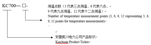
Types and Meanings of KC700
Installation
1) Installation instructions for wireless temperature measurement receiver
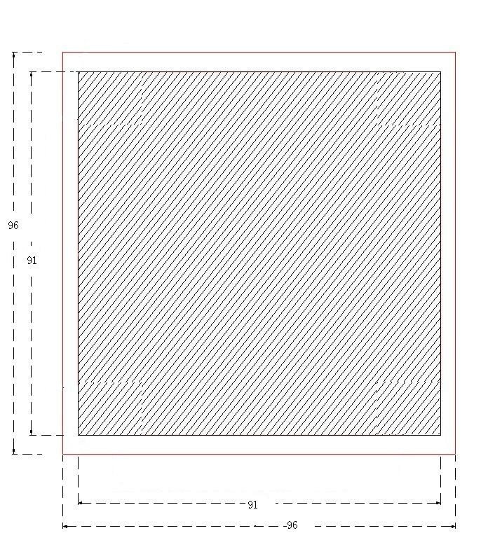
①Installation dimension drawing
(The size of the digging hole is 91*91MM)
②Receiver terminal wiring diagram
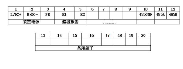
Note: ①②③Working power supply AC/DC110~220V;④⑤Over temperature alarm output, normally open contact; ⑩⑪⑫RS485 communication interface.
2) Installation instructions for wireless temperature measurement transmitter
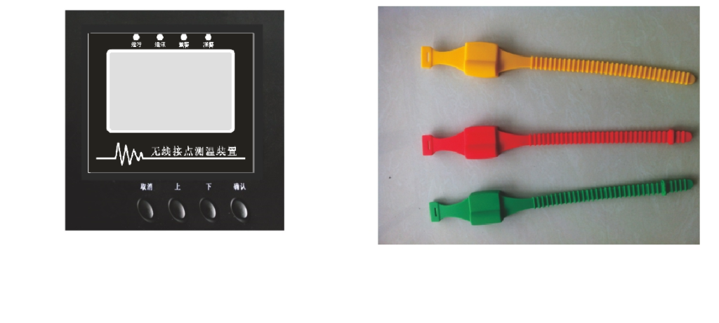
①Contact temperature measurement unit structure
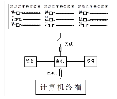
The wireless temperature measurement online detection device consists of a wireless temperature measurement receiver, a temperature measurement transmitter module, a temperature measurement collection receiver module (inside the assembled receiver) and an external antenna.
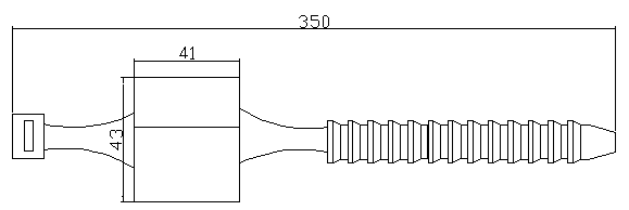
②Wireless temperature sensor size and parameters
Installation dimension drawing: (unit: mm)
Features and Parameters
- Temperature-resistant (-180℃~+250℃) flame retardant material to make plastic strap shell, waterproof.
- The thermal sensor in the body is in close contact with the contact body, which can accurately measure the real-time temperature.
- The launch distance of the inner module is 20 to 30 meters.
- Temperature measurement range -55℃~125℃.
3) Installation
The temperature measurement and emission modules are installed on the busbars of the incoming and outgoing compartments of the switch cabinet, and the installation method is bundled installation.
- Put the strap-shaped temperature measurement module on the object to be measured.
- Pass one end of the strap-shaped temperature measuring module through the other end.
- Until the strap-shaped temperature measuring module is tightly sleeved on the object to be measured.
- Cut off the strap of the extended part.
- The cabinet should be powered off during installation.
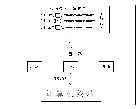
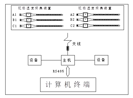
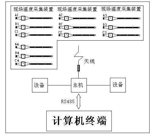
4) Schematic diagram of wireless temperature measurement
a.3-way wireless temperature measurement transmitter module: the color is (yellow, green, red), and the label is (A1, B1, C1).
b.6-way wireless temperature measurement transmitter module: the color is (yellow, green, red), the incoming room is (A1, b1, C1), and the outgoing room is (A2, b2, C2).
c. 9-way wireless temperature measurement transmitter module: the colors are (yellow, green, red), respectively marked as (A1, b1, C1); (A2, b2, C2); (A3, b3, C3)
d.12-way wireless temperature measurement transmitter module: the colors are (yellow, green, red), respectively marked as (A1, b1, C1); (A2, b2, C2); (A3, b3, C3); (A4, b4, C4).
Display and Setting Instructions
The data display will show the measured data. Each time you press the “Down” key to scroll down a screen, and automatically return to the first screen after reaching the last screen. When the automatic cycle is displayed, the factory default of this device is to flip a screen every 5 seconds
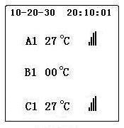
1) Display
Temperature display: The temperature of the A1 road is 27℃, the B1 road shows that the contact has no signal, the C1 road temperature is 27℃, and the real-time time is displayed. Select the “Enter” button to enter the main menu.
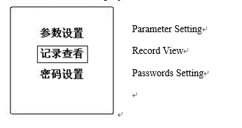
2)main menu
Press “Up” and “Down” keys to move the menu, and press “Enter” key to enter the corresponding menu, and press “Cancel” to return to the display interface.
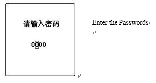
3) Password input
After selecting “Parameter Setting”, you will be prompted to enter the corresponding password, the factory password is “0000”, enter the correct password to enter the parameter setting menu.
4) Parameter setting
Press the “Up” and “Down” keys to move the menu, and press the “Enter” key to enter the corresponding menu, and press “Cancel” to return to the main menu interface.
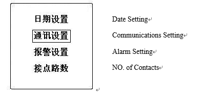
5) Date setting
Enter the “Date Setting” interface, press the “Cancel” button to move the number to be modified, press the “Up” and “Down” buttons to change the data size, confirm to save the data, and enter the parameter setting interface.
6) Communication settings
Select “Communication Settings” in the parameter setting interface, after entering the “Cancel” key to move the position, press the “Up” and “Down” keys to change the size of the data, and press the “Enter” key to save the setting data and enter the parameter setting menu
7) Alarm settings
Select “Alarm Setting” in the parameter setting interface, press the “Up” and “Down” keys to change the size of the alarm upper limit data, and press the “Enter” key to save the setting data and enter the parameter setting menu.
8) Number of Contacts
In the parameter setting interface, select “Number of Contacts”, press the “Up” and “Down” keys to change the number of channels, and press the “Enter” key to save the setting data and enter the parameter setting menu.
9) Record query
Enter the “Record View” interface in the main menu. When there is a fault record, it will display the time and temperature corresponding to the over-temperature occurrence. Press the “Up” and “Down” buttons to turn the page. At the last page, it will prompt, “Whether or not Clear record” prompt, confirm to clear, cancel to return to the main menu.
10) Password setting
Enter the “Password Setting” interface in the main menu, select the location by pressing the “Cancel” button, and change the data size by pressing the “Up” and “Down” buttons. If the password is changed successfully, if the original password is entered incorrectly, it will be prompted to change the password.